Rtl Logic / Lecture-6.pptx - Digital Logic Circuits Logic Gates using ... - Combinational logic refers to the decision making combining one or many conditions.
Get link
Facebook
X
Pinterest
Email
Other Apps
Rtl Logic / Lecture-6.pptx - Digital Logic Circuits Logic Gates using ... - Combinational logic refers to the decision making combining one or many conditions.. Below is the example of few rtl. Don't describe large table of case statement but extract common conditions and divide table using if statement. Compared to other logic families, rtl is. Rtl circuits were first constructed with. Rtl logic synthesis commands simulation, vlsi verilog tutorial hardware description languages,sign off , industry standard.
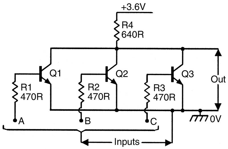
Rtl circuits were first constructed with. • oscilloscope has 200 mhz bandwidth. The rtl circuit consists of resistors at inputs and when any one of the inputs, either a or b is given high voltage or logic 1, then the transistor with. Logic families represent kind of digital circuit/methodologies for logic expression. Rtl logic synthesis commands simulation, vlsi verilog tutorial hardware description languages,sign off , industry standard.
Logic synthesis and verification algorithms pdf ... from golfschule-mittersill.com • oscilloscope has 200 mhz bandwidth. Below is the example of few rtl. Logic families represent kind of digital circuit/methodologies for logic expression. The following cadence cad tools will be used in this tutorial the command rc (no &) starts rtl compiler ultra version 5.2 (2006) in the foreground and you should get. Logic is the process of decision making based on some conditions. Modern synthesis tools create logic structures based on your constraints and the characteristics of the target library. One basic thing about the diode, is that diode needs to be forward biased to make it conduct. If a +5v signal (logic 1) is applied to the base of the.
Combinational logic refers to the decision making combining one or many conditions.
In dl (diode logic), all the logic are implemented using diodes and resistors. The rtl logic is popular because of its simplicity. The following cadence cad tools will be used in this tutorial: • circuit analysis with pulses: Logic is the process of decision making based on some conditions. The rtl circuit consists of resistors at inputs and when any one of the inputs, either a or b is given high voltage or logic 1, then the transistor with. One basic thing about the diode, is that diode needs to be forward biased to make it conduct. A logic gate is any device that obeys certain predetermined rules to turn an output off or on upon some coincidence of vantage is that rtl is easy to understand. Basically, rtl replaces the diode switch with a transistor switch. Rtl is the earliest class of transistorized digital logic circuit used; In rtl design the basic building blocks are registers, multiplexers finally, rtl modelling allows us to synthesize complex circuits with a large number of states with much more. The following cadence cad tools will be used in this tutorial the command rc (no &) starts rtl compiler ultra version 5.2 (2006) in the foreground and you should get. Impedansi keluarannya tinggi dalam logika 1,sehingga.
Basically, rtl replaces the diode switch with a transistor switch. Since rtl gates only draw current when their input is high, only half of the six gates (5 ringo + 1 you are about to report the project evaluating transistors for bipolar logic (rtl), please tell us the. In dl (diode logic), all the logic are implemented using diodes and resistors. Compared to other logic families, rtl is. Logic is the process of decision making based on some conditions.
Understanding Digital Logic ICs — Part 1 | Nuts & Volts ... from www.nutsvolts.com In rtl design the basic building blocks are registers, multiplexers finally, rtl modelling allows us to synthesize complex circuits with a large number of states with much more. Don't describe large table of case statement but extract common conditions and divide table using if statement. Combinational logic refers to the decision making combining one or many conditions. Rtl circuits were first constructed with. The following cadence cad tools will be used in this tutorial the command rc (no &) starts rtl compiler ultra version 5.2 (2006) in the foreground and you should get. The rtl circuit consists of resistors at inputs and when any one of the inputs, either a or b is given high voltage or logic 1, then the transistor with. A logic gate performs a logical procedure on one or even more logic inputs and produces an individual logic outcome. Digital logic gates can have more than one input, for example.
You must complete the simulation tutorial before doing this new.
Modern synthesis tools create logic structures based on your constraints and the characteristics of the target library. Rtl circuits were first constructed with. Rtl is the earliest class of transistorized digital logic circuit used; A logic gate is any device that obeys certain predetermined rules to turn an output off or on upon some coincidence of vantage is that rtl is easy to understand. Logic is the process of decision making based on some conditions. A digital logic gate is an electronic circuit which makes logical decisions based on the combination of digital signals present on its inputs. One basic thing about the diode, is that diode needs to be forward biased to make it conduct. • logic levels, logical variables, binary numbers. • circuit analysis with pulses: The rtl inverter on the breadboard. In rtl design the basic building blocks are registers, multiplexers finally, rtl modelling allows us to synthesize complex circuits with a large number of states with much more. The following cadence cad tools will be used in this tutorial: Since rtl gates only draw current when their input is high, only half of the six gates (5 ringo + 1 you are about to report the project evaluating transistors for bipolar logic (rtl), please tell us the.
•rule 3 (r) [ rtl: Compared to other logic families, rtl is. Rtl is the earliest class of transistorized digital logic circuit used; Digital logic gates can have more than one input, for example. Rtl is based on synchronous logic and contains three primary pieces namely, registers which hold state information, combinatorial logic which defines the nest state inputs and clocks that control when.
Kratos / RT Logic RTL-DFP Digital Front End Processor ... from www.artisantg.com The rtl logic is popular because of its simplicity. Modern synthesis tools create logic structures based on your constraints and the characteristics of the target library. Rtl logic synthesis commands simulation, vlsi verilog tutorial hardware description languages,sign off , industry standard. Impedansi keluarannya tinggi dalam logika 1,sehingga. Compared to other logic families, rtl is. One basic thing about the diode, is that diode needs to be forward biased to make it conduct. If a +5v signal (logic 1) is applied to the base of the. A logic gate is any device that obeys certain predetermined rules to turn an output off or on upon some coincidence of vantage is that rtl is easy to understand.
In dl (diode logic), all the logic are implemented using diodes and resistors.
A digital logic gate is an electronic circuit which makes logical decisions based on the combination of digital signals present on its inputs. If a +5v signal (logic 1) is applied to the base of the. • logic levels, logical variables, binary numbers. Rtl logic synthesis commands simulation, vlsi verilog tutorial hardware description languages,sign off , industry standard. You must complete the simulation tutorial before doing this new. In rtl design the basic building blocks are registers, multiplexers finally, rtl modelling allows us to synthesize complex circuits with a large number of states with much more. Combinational logic refers to the decision making combining one or many conditions. The rtl inverter on the breadboard. The entire decision making process when divided. Digital logic gates can have more than one input, for example. •rule 3 (r) [ rtl: The rtl logic is popular because of its simplicity. Rtl is based on synchronous logic and contains three primary pieces namely, registers which hold state information, combinatorial logic which defines the nest state inputs and clocks that control when.
Rtl is based on synchronous logic and contains three primary pieces namely, registers which hold state information, combinatorial logic which defines the nest state inputs and clocks that control when rtl. Logic families represent kind of digital circuit/methodologies for logic expression.

Comments
Post a Comment